
Introduction
Talking about aluminum die-casting tolerances is probably the most productive conversation you can have in the precision manufacturing world. If you are any engineer who has ever put a drawing on a die caster with the notation “±0.02 mm all over,” you have been told by about the same factor at least once.
Aluminum die casting is still fundamentally constrained by the physics of molten metal solidifying under high pressure in a steel mold; it does provide high production rates, exceptional dimensional consistency, and excellent surface finish. Knowing the true capacity of an as-cast aluminum can, when secondary machining is necessary, and how industry requirements like NADCA and ISO 8062-3 define those limits makes the difference between cost-effective and problematic, and expensive parts.
This article offers:
- An easy-to-follow numbers-based reference for aluminum die casting tolerances.
- It includes information on the actual capabilities of modern high-pressure die casting.
- The distinction between standard and precision grades.
- The effect of part geometry and process variables.
- The features that are virtually always subject to machining, and the proper specification of tolerances on a casting drawing.
The following information will help you establish expectations for the gearbox housing, electronic enclosure, or structural automotive part you are designing.
What As-Cast Aluminum Can Realistically Hold
Die casting is a process that involves forcing molten aluminum at high speeds and pressures into a hardened steel die. The metal is shrinking as it is solidifying and cooling. This shrinkage, along with the mechanical limitations of the mold, the position of the parting line, and the uniformity of the wall thickness, determines the lowest tolerances that can be met as-cast.
The following are the typical working tolerances for common production lines of aluminum alloys, A380 and ADC12:
| Feature Dimension | Typical As-Cast Tolerance | Best Case (Careful Process Control) |
| Up to 25 mm | ±0.10 mm | ±0.07 mm |
| 25 – 100 mm | ±0.15 mm | ±0.10 mm |
| 100 – 250 mm | ±0.25 mm | ±0.18 mm |
| 250 – 500 mm | ±0.35 mm | ±0.25 mm |
| Holes/core pins (diameter) | ±0.10 mm | ±0.07 mm |
| Flatness per 100 mm | ±0.20 mm | ±0.10 mm with proper die design |
Slides and cores are used to create dimensions that extend over the parting line, which are given extra allowance. The numbers move most due to three factors:
Distance between the parting line and the area
The features that overlap both parts of the mold have a larger range. As far as possible, the critical flat or sealing faces should be on one side of the mold.
Wall thickness uniformity
A sudden casting, where the 2 mm suddenly changes to 6 mm, will be pulled and distorted as it cools. The requirement of uniform walls is not a design preference; it is a requirement to have the tighter end of the tolerance bands.
Alloy selection
The alloys that contain silicon have more regular shrinkage than other alloys that are softer or stronger. When a design created for a machined 6061 product is adapted to die casting, the tolerance section almost always will have to be revised.

NADCA and ISO Standards: Aluminum Die Casting Tolerances
There are two main standards that are most popular– North American Die Casting Association (NADCA) Product Specification Standards and ISO 8062-3.
The difference between NADCA Standard and Precision Tolerances
There are two practical levels from NADCA.
- Standard Tolerance is the tolerance that a competent caster is capable of holding at full production speed with reasonable die life and normal inspection.
- Precision Tolerance is a tighter tolerance band that is only used for features whose form, fit, or function is sensitive to small tolerances.
Standard is the lowest cost and meets most applications. An agreed-upon precision feature selected in the early stages may sometimes be accomplished with only a moderate additional expense.
Both standard and precision values are provided for linear dimensions, parting-line adders, slide/core adders, angularity, draft, flatness and cored-hole diameters. A standard value is given for concentricity and parting-line shift.
The casting tolerance grades are defined in ISO 8062-3
Castings are graded according to ISO 8062-3 from DCTG 1 (finest) to DCTG 16 (coarsest). The recommended grade varies for aluminum and magnesium pressure die castings, depending on the largest overall dimension of the part:
| Largest Overall Dimension | Recommended Grade (Aluminum & Magnesium) |
| Up to 50 mm | DCTG 6 |
| Over 50 mm up to 180 mm | DCTG 7 |
| Over 180 mm up to 500 mm | DCTG 8 |
| Over 500 mm | DCTG 9 |
These grades are based on a reasonably long production run and a developed process. Complex geometries are typically quoted one grade lower. The wall thicknesses are assumed to be one grade thicker than the general linear tolerance. Total values for the tolerances of these grades are higher with increasing nominal size: a feature of 100–160 mm at DCTG 8 has a total tolerance of 1.8 mm (±0.9 mm).
ISO does not use a plus-only parting-line adder as NADCA does. Explicitly specify an asymmetric tolerance on the dimension if a greater tolerance is required in one direction than the other.
Features for Post-Casting Machining: Essential
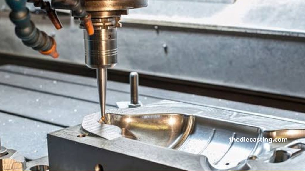
Some of these characteristics can only be maintained to the necessary precision if the process is controlled carefully, but not if the casting is done as cast:
- Precision bores and bearing seats. Generally, anything that a bearing or seal rides on requires ±0.02 to ±0.05 mm. A tolerance of 0.3 to 0.8 mm of stock should be planned for machining.
- Flat sealing faces. A facing pass is almost always applied to gasket and O-ring surfaces.
- The following M6 threads are tapped. Small threads can be cut or formed after being cast; larger cast-in threads are possible.
- Concentricity (or true-position relationships) smaller than about ± 0.03 mm. These features should be machined in a single set up from the same datum.
To allow intentional machining stock in just those faces to allow the finishing operation to remove clean metal and not engage residual warp or shrinkage variation in the mold.
Tolerances on a Casting Drawing
There are four practical rules to be followed in making drawings:
- Tightly mark the functional faces. Precision or individual tolerances are applied to bearing seats, sealing faces, mating threads, and alignment features.
- Allow surfaces that don’t perform a function to breathe. As cast tolerances on non-critical dimensions are standard, they also come without additional cost and do not restrict the process.
- Prefer GD&T for positional relationships. It is a straightforward callout and much easier for a supplier to quote and check than a pile of bilateral linear tolerances.
- Explicitly identify which faces will be machined. The caster can then form the proper stock allowance during the forming process.
A general tolerance note in or adjacent to the title block should refer to either NADCA Section 4A (Standard or Precision) or ISO 8062-3 and the relevant DCTG grade. Individual tighter tolerances are specified only where needed to override the general note.
Factors That Limit Achievable Tolerance
However, many physical and process factors limit the amount that can be stored even in the published tables:
Part size and shape
These are the most challenging and are usually large, thin-walled, or abrupt changes in wall thickness.
Wear and alignment of the dies
A gradual increase in the amount of shifting occurs between the two halves over the life of the tool.
Clamping force
When the machine size is not adequate for the area to be produced, the die will open up a little bit under the injection pressure, creating some variation in each of the dimensions that cross the parting line.
Shrinkage properties and solidification of alloys
Final dimensions are affected by process parameters such as metal temperature, velocity profile, die temperature, and cycle timing.
If a tolerance is required that is more precise than the NADCA precision for the feature length or the corresponding ISO for the feature length, the economical answer is nearly always to cast with stock and machine the feature.
Methods of Quality Control for ensuring Tolerance Capability
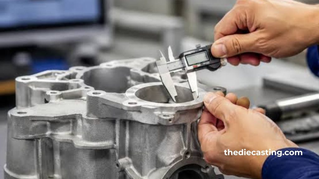
Today’s modern aluminium die casting facilities incorporate conventional gauging with modern non-destructive techniques and statistical process control. Coordinate measuring machines are used to check first articles and, on a sample basis, critical dimensions.
However, if internal porosity or cold shut is found during real-time X-ray or, if warranted by the situation, during on-line CT, it can be a sign of an integrity issue even if the external dimensional tolerances are met. Key process variables and capability keys are tracked using statistical process control to ensure that the process is corrected before parts are out of specification.
Ppk is sometimes needed to be greater than 1.67 at PPAP for critical characteristics. Since new dies are designed with intentional tolerances for wear, so that the dimensions are closer to the nominal, NAO (as-cast) is more applicable to assess the feature using Cp rather than Cpk.
Practical Guidelines for Designers and Procurement Teams
Whenever possible, keep all main datums in one die half and off slides. Dimensions measured from a datum in the opposite half automatically pick up parting-line and shift adders.
- Use a draft early (usually of 1-3° depending on draft depth) to prevent distortion of the part by the ejection force.
- Select alloys that have a known shrinkage, if close as-cast tolerances are needed.
- Communicate with the caster at the design phase about parting line, draft, datum scheme, and the features that will be machined.
- Machining stock: 0.3 to 0.8 mm is left for most aluminum components 100 – 300 mm in size. The volume of stock should not be too high, or it wastes material and cycle time, nor too low, or the cleanup will not be complete.
- The functional requirements and cost, all considered, can be met with aluminum die castings, routinely, using these practices.

Frequently Asked Questions
What are the common tolerances for the aluminum die casting?
Under normal production conditions, the as-cast linear tolerances of aluminum are normally ±0.10 mm for a value below 25 mm, and ±0.25–0.35 mm for a value larger than 25 mm. The formal reference is provided by NADCA Standard or Precision tables or ISO 8062-3 tables (DCTG 6–9 if overall part size).
Is it possible to die cast aluminum?
Yes. Aluminum is one of the most commonly die-cast metals in the world. A380, ADC12, and A356 are among the many alloys commonly used on both hot-chamber (less common for aluminum) and cold-chamber high-pressure die casting machines. They create complex geometries, thin walls, excellent surface finish, and high production rates for automotive, electronics, industrial, and consumer applications.
Can 6061 aluminum be used for casting?
6061 is a very good wrought alloy, and not a desirable alloy for die casting. It is not as well suited for high-pressure die casting as the dedicated casting alloys, A380 or ADC12, because of its solidification properties, fluidity, and shrinkage. The mechanical property specifications for the material of the original design are nearly always different when the design is transferred to die casting, and it is also frequently necessary to change the tolerances on the material.
What are the normal tolerances of aluminum?
In regard to die casting, but outside of the specific process, the term “standard tolerances for aluminum” can apply to a number of processes (extrusion, machining, sheet metal, etc.). In high-pressure die casting, the relevant standards are the NADCA Product Specification Standards (Section 4A) and ISO 8062-3. The typical as-cast tolerance is about ±0.10 mm, which increases with feature size, and precision grades have slightly smaller bands on some dimensions.
Conclusion
Aluminum die casting offers excellent productivity and complexity, but its dimensional ability is ultimately limited by solidification physics, die design, and process control. The practical cast tolerances of ±0.10 mm for small features and ±0.25-0.35 mm for larger features are realistic and economical based on the standard or ISO 8062-3 guidelines of NADCA.
Selected dimensions can be further tightened with precision grades and controlled processes, but it is almost always necessary to intentionally machine stock and perform secondary operations to ensure critical bores, sealing faces, and close positional relationships.
Have experienced die casters involved at the early stage, define the tolerances that count, and aluminum die casting is an extremely effective way to get precision parts that assemble easily and reliably in production.